Recently I've been working on a Quake BSP renderer. I've been trying to reverse engineer as much as I can from descriptions of the Quake engine found on the internet. One thing that's not described very well is how Quake handles the sky. This post will describe how this is implemented in other engines and how I ended up implementing it.
First a video of how it should look. This is taken from the intro level in vkQuake.
Next some details I could gather about how Quake renders skies:
Not really enough information to recreate the effect so I decided to take a look at how vkQuake does it. RenderDoc shows roughly how the level is rendered.
vkQuake renders a simple flat-colored version of the sky and then fills it in.
Setting r_fastsky will skip the second step, presumably offering some performance improvements.
Since modern hardware is so fast, this can be left out.
The detailed pass is somewhat odd in that it is rendering several small squares instead of the same regions filled in by the fastsky pass. These squares are not present in the actual BSP file for the level. The BSP geometry looks something like this:
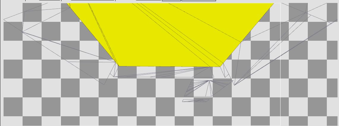
vkQuake generates these tiles at runtime from the extents of the whole skybox. I.e. the minimum and maximum of the skybox along each of the X, Y and Z axes. Each skybox face is aligned along one of these axes. So when it is time to render that face it is extended along the extents for that axis and split up into tiles before being rendered. See gl_sky.c for more detail.
This is somewhat complicated and results in some overdraw. Maybe there is a simpler approach?
It shouldn't be necessary to render these squares since the entire area to be filled is covered by the sky meshes that are already present in the BSP. Simply rendering them with no animation and with the normal Quake texture coordinates results in this:
This screenshot shows what the actual level geometry looks like, but the perspective is incorrect. The sky is supposed to be infinitely far away from the observer. Here, since it is part of the level geometry it is actually really close. Luckily there is a way to fake this distance without messing with the actual vertices.
If the observer is very far away from the sky then the position of the observer should not have any effect on how it is displayed. If you're out walking you don't see clouds getting any closer. It's like they're fixed in place. However, turning your head will show you different parts of the sky. So the part of the texture we're rendering depends only on the vector between the point being rendered and the observer.
I passed the location of the camera as a uniform and subtracted it from the position to get this vector:
vec3 dir = inPosition - uniforms.origin;
Next, the vector should be normalized. This is because the sky is supposed to be very far away, so how close you actually are to the point should have no effect on the final calculation.
dir = normalize(dir);
Finally project the vector onto the texture space. (Actually the front and back texture need separate tex coords, but for now set them to the same vector.)
vec2 texCoord = vec2(dir.x, dir.z);

This looks vaguely correct, except the scale is slightly off and it's not animated. There isn't really a way to reverse engineer the scale, but looking at vkQuake source gives the following for computing the texture coordinates:
            void Sky_GetTexCoord (vec3_t v, float speed, float *s, float *t)
            {
                vec3_t	dir;
                float	length, scroll;

                VectorSubtract (v, r_origin, dir);
                dir[2] *= 3;	// flatten the sphere

                length = dir[0]*dir[0] + dir[1]*dir[1] + dir[2]*dir[2];
                length = sqrt (length);
                length = 6*63/length;

                scroll = cl.time*speed;
                scroll -= (int)scroll & ~127;

                *s = (scroll + dir[0] * length) * (1.0/128);
                *t = (scroll + dir[1] * length) * (1.0/128);
            }
The length variable here is using the dot product to compute the square of the magnitude of the vector.
The call to sqrt converts this to the magnitude.
Next it is multiplied by 6*63.
Finally length is multiplied by the X and Z axes of the dir vector.
(Note that in the Quake sources, Z is the 2nd axis and Y is the 3rd.)
This is doing the same as normalizing the vector and then scaling it by a constant.
Multiplying the Y axis is skipped since it's not used in the final calculation.
The multiplication by 1/128 is scaling by the height/width of the texture. This is necessary to go from world space coordinates to texture coordinates.
The scroll variable has to do with the animation effect so it can be ignored for now.
So all that should be necessary to fix the scaling would be a multiplication by 6*63 and a division by 128.
vec3 dir = normalize(dir) * 6*63 / 128.f;

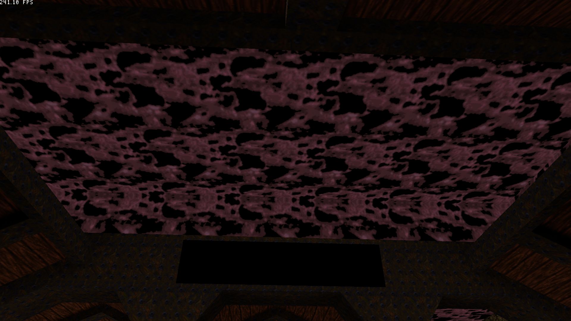
This looks better but still odd. Up close, the problem is a bit more clear.

It's still not obvious what's wrong. Maybe adding animation will make it more so. This is done by simply offsetting the texture coordinates by some time dependent variable. First a uniform with the current elapsed time needs to be added.
            float scroll = uniforms.elapsedS;

            texCoord = vec2(scroll + dir.x, scroll + dir.z);
It's a bit fast, plus it's going in the wrong direction. This is probably another scaling issue. Here I experimentally determined that division by 8 produced a similar effect to Quake. The back texture also needs to be scrolled at a slower speed than the front one to produce the parallax effect. Finally, flipping some signs fixes the direction.
            float scroll = uniforms.elapsedS / 8;
            outTexCoordFront = vec2(scroll + dir.x, scroll - dir.z);
            scroll /= 2;
            outTexCoordBack = vec2(scroll + dir.x, scroll - dir.z);
Or, more closely:
It looks like there is some discontinuity between the triangles that make up this face. Because some of the triangles in the geometry here are so small it looks like there are some interpolation errors with the texture coordinates. This is because each triangle only takes into account the values of the texture coordinates at each of its three vertices instead of interpolating based on the vertices for the entire face. This kind of thing can happen with Gouraud shading as well and the solution there is to interpolate normals and perform the final calculation in the fragment shader. Moving the final calculations to the fragment shader yields a vertex shader that looks like this:
            #version 450
            #extension GL_ARB_separate_shader_objects : enable

            #include "uniforms.glsl"

            layout(location=0) in vec3 inPosition;
            layout(location=1) in vec2 inTexCoord;
            layout(location=2) in uint inTexIdx;
            layout(location=3) in vec2 inLightCoord;
            layout(location=4) in int inLightIdx;
            layout(location=5) in vec2 inExtent;

            layout(location=0) out flat uint outTexIdx;
            layout(location=1) out vec3 dir;

            void main() {
                gl_Position = uniforms.mvp * vec4(inPosition, 1.0);
                outTexIdx = inTexIdx;

                dir = inPosition - uniforms.origin;
            }
All that's being done here is computing the vector from the camera to the vertex, which is then interpolated before being passed to the fragment shader. That fragment shader looks like this:
            #version 450
            #extension GL_ARB_separate_shader_objects : enable

            #include "uniforms.glsl"

            layout(binding=1) uniform sampler2D atlas[2];

            layout(location=0) in flat uint inTexIdx;
            layout(location=1) in vec3 inDir;

            layout(location=0) out vec4 outColor;

            void main() {
                vec3 dir = inDir;
                dir.y *= 3;
                dir = normalize(dir) * 6*63 / 128.f;

                float scroll = uniforms.elapsedS / 8.f;
                vec2 texCoordFront = vec2(scroll + dir.x, scroll - dir.z);

                scroll = scroll / 2.f;
                vec2 texCoordBack = vec2(scroll + dir.x, scroll - dir.z);

                vec3 frontColor = texture(atlas[inTexIdx], texCoordFront).rgb;
                vec3 backColor = texture(atlas[inTexIdx+1], texCoordBack).rgb;
                vec3 color = frontColor;
                if (frontColor.x + frontColor.y + frontColor.z < .01f) {
                    color = backColor;
                }
                outColor = vec4(color, 1);
            }
Note a minor refinement is that I added the dir.y *= 3 from the vkQuake code.
Not adding this results in a much more curved sky.
Similarly the scroll value has been tweaked a bit.
Finally, if the front color is close enough to black it's swapped for the back color.
(These textures are masked such that black colors are supposed to be transparent).
This results in an effect that looks like this:
This effect is close enough to the original that I'm happy with it.
The final insight about the interpolation was a bit of a head scratcher. I'd say the main lesson from this exercise was to be careful what you interpolate!